Trace six instructions through a five-stage pipeline
Trace six independent instructions through a declared five-stage pipeline, calculate fill and drain overhead, and distinguish bubbles from global stalls.
A five-stage pipeline overlaps work on different instructions. It does not finish one instruction in a fifth of its original time. If you read assembly or compare CPU designs, start by separating three quantities: an instruction’s latency, the interval between completed instructions, and the total time for a finite batch.
Use a deliberately hypothetical single-issue processor with fetch, decode/register read, execute, memory and writeback stages, abbreviated IF, ID, EX, MEM and WB. Each instruction spends one complete cycle in every stage. Registers capture results at the end of a cycle, and the next stage uses those captured values in the following cycle. This is a teaching schedule, not a timing model for every RISC-V implementation.
Choose instructions that satisfy the simple schedule
Let x20 initially contain 100 and leave it unchanged. Six illustrative RV32 additions write distinct destination registers:
addi x1, x20, 1
addi x2, x20, 2
addi x3, x20, 3
addi x4, x20, 4
addi x5, x20, 5
addi x6, x20, 6
Call these instructions I1 through I6 in their listed order. None consumes a destination produced by another instruction in the batch. There are no branches, faults or interrupts, and instruction delivery never misses or stalls. Assume the implementation has the resources needed to perform the scheduled stages concurrently. These conditions establish the simple trace; the stage names alone do not.
The arithmetic instruction carries its result through MEM without a data-memory access. This fixed pipeline still uses its MEM cycle: skipping a stage for selected instructions would define a different schedule. The RV32 base specification defines ADDI’s architectural arithmetic, while the timing assumptions here are explicitly invented.
Place each instruction on the cycle chart
I1 occupies IF during cycle one, ID during cycle two, EX during cycle three, MEM during cycle four and WB during cycle five. Its register write occurs at the end of cycle five. Meanwhile, I2 starts IF in cycle two and reaches WB in cycle six. The same diagonal shift applies to the remaining instructions.
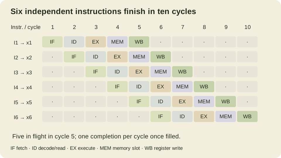
Read the chart in both directions. A row follows one instruction through time. Column five contains I5 in IF, I4 in ID, I3 in EX, I2 in MEM and I1 in WB. There are five instructions in flight, but only I1 finishes in that cycle. Confusing occupancy with completions would incorrectly turn a single-issue pipeline into a five-instruction-per-cycle machine.
The first completion takes five cycles from an initially empty pipeline. Each remaining instruction adds one cycle when the stream is uninterrupted. Therefore a nonempty batch of N instructions completes in N plus four cycles under these assumptions. Six instructions take ten cycles, and their batch-average cycles per instruction is ten divided by six, or five thirds. The steady-state completion interval is still one cycle.
The Computation Structures pipelined-Beta lecture develops the five-stage overlap and the hazards that disturb it. Its register-file and ALU stage names differ slightly from this chart. Its memory timing is also specific to that teaching processor; do not transfer that detail into a generic claim about all five-stage pipelines.
Carry the instruction’s identity with its result
A pipeline register must retain more than a numeric answer. Later stages also need the destination register, whether a write is enabled, and other control information relevant to that instruction. Pairing I3’s result with I4’s destination would corrupt architectural state even if every arithmetic value was computed correctly.
The following executable model carries identity, destination and precomputed result together. It checks stage occupancy and writes at the modeled WB boundary. It does not decode or execute the assembly: the six arithmetic results are calculated directly from the declared operands to isolate scheduling and bookkeeping.
from fractions import Fraction

STAGES = ("IF", "ID", "EX", "MEM", "WB")
MASK32 = (1 << 32) - 1

def trace(admissions, initial=100):
    pipeline = [None] * 5
    rows, commits, registers = [], [], {}
    for cycle in range(1, len(admissions) + 5):
        index = admissions[cycle - 1] if cycle <= len(admissions) else None
        token = None if index is None else (
            index, index + 1, (initial + index + 1) & MASK32)
        pipeline = [token] + pipeline[:-1]
        rows.append(tuple(None if item is None else item[0] + 1
                          for item in pipeline))
        if pipeline[-1] is not None:
            identity, destination, value = pipeline[-1]
            assert destination == identity + 1
            registers[destination] = value
            commits.append((cycle, identity + 1))
    return rows, commits, registers

rows, commits, registers = trace(list(range(6)))
assert rows[4] == (5, 4, 3, 2, 1)
assert commits == [(i + 5, i + 1) for i in range(6)]
assert registers == {i: 100 + i for i in range(1, 7)}
assert Fraction(commits[-1][0], 6) == Fraction(5, 3)

# Two idle admission slots; older instructions continue advancing.
_, delayed, same_registers = trace([0, 1, None, 2, 3, None, 4, 5])
assert delayed == [(5, 1), (6, 2), (8, 3), (9, 4), (11, 5), (12, 6)]
assert same_registers == registers
_, _, wrapped = trace(list(range(6)), initial=0xfffffffd)
assert wrapped == {1: 0xfffffffe, 2: 0xffffffff, 3: 0, 4: 1, 5: 2, 6: 3}

logic_ps = (180, 160, 210, 190, 120)
register_budget_ps = 30
clock_ps = max(logic_ps) + register_budget_ps
unsegmented_ps = sum(logic_ps) + register_budget_ps
assert (clock_ps, unsegmented_ps) == (240, 890)
assert 5 * clock_ps == 1200
assert commits[-1][0] * clock_ps == 2400
assert Fraction(6 * unsegmented_ps, 10 * clock_ps) == Fraction(89, 40)
print("six-instruction schedule, two bubbles, 32-bit results and timing budget checked")
The wraparound case changes the common source value to 0xFFFFFFFD while preserving independence. It tests that the model keeps 32-bit arithmetic as declared. It does not turn the timing chart into a proof of instruction decoding, exception behavior or forwarding. Those are separate mechanisms that the simple token model intentionally omits.
Convert cycles to time using the slowest stage
Assume invented combinational stage delays of 180, 160, 210, 190 and 120 picoseconds. Add thirty picoseconds per clock interval as a combined register and timing budget. The limiting stage is EX at 210 picoseconds, so the modeled pipeline period is 240 picoseconds. Adding the five logic delays and dividing by five would ignore the slowest stage and permit a clock that some paths cannot meet.
For a deliberately matched unsegmented comparison, assume the five logic delays lie on one serial path and use the same thirty-picosecond endpoint budget. Its interval is 890 picoseconds. These numbers are assumptions for arithmetic, not delays extracted from a chip, synthesis report or standard-cell library. Real setup, hold, clock skew and physical path constraints need their own timing analysis.
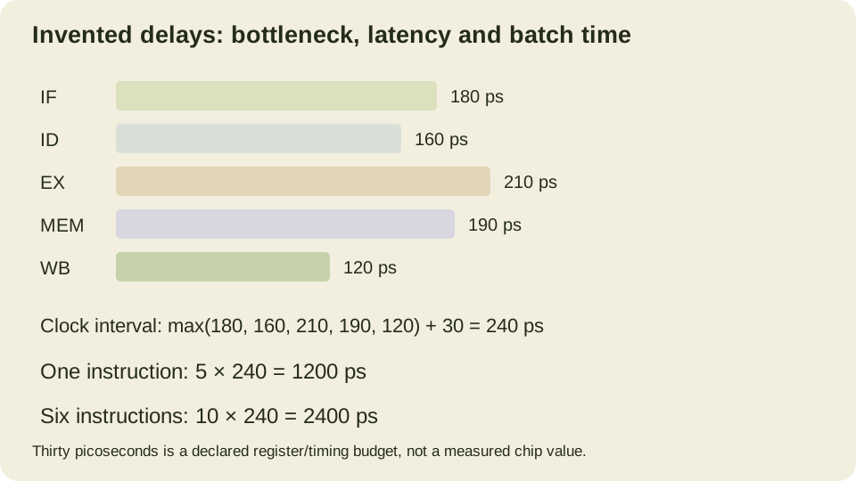
One pipelined instruction takes 1,200 picoseconds, which is longer than the unsegmented interval of 890. Six unsegmented instructions take 5,340 picoseconds; the pipelined batch takes 2,400. The batch speedup is 2.225, not five. For very long uninterrupted streams, the throughput ratio approaches 890 divided by 240, approximately 3.708. Finite fill and drain overhead explains why the six-instruction gain is smaller.
The performance notes on latency and pipelined circuits distinguish these metrics and explain why registers can improve throughput while increasing latency. Adding another stage helps throughput only if it reduces the limiting interval enough to justify its extra register budget. A stage count by itself is not a clock-frequency measurement.
Model a bubble without calling it a global stall
The second schedule inserts two empty admission slots, before I3 and before I5. Older instructions continue moving. Those empty slots travel through the stages and create gaps between completions. The final instruction now finishes at the end of cycle twelve, while the register values and instruction order are unchanged.
This is an admission-bubble model. A real hazard may instead hold some pipeline registers while letting others advance, or block the whole pipeline. A cache miss can require a different state machine and a much longer delay. Do not claim that every two-cycle disruption simply inserts these same two slots unless the implemented control rule matches the model.
As an exercise, insert one empty admission slot immediately before I6 and predict its completion cycle. Then imagine a stall that freezes every occupied stage for one cycle after cycle three. Draw that second case separately: the affected intermediate positions differ even if a selected total-time count happens to match. Naming what advances and what holds makes a pipeline timing claim reviewable.