Decode an RV32I add instruction field by field
Decode 0x007302B3 into RISC-V ADD fields, reconstruct the instruction word, and distinguish ISA facts from processor timing.
Decoding an RV32I instruction means assigning meaning to fixed bit fields in a 32-bit word. If you are reading compiler output, start with one instruction whose operands are easy to recognize: add x5, x6, x7. Its encoding is 0x007302B3, and every part of that number has a defined role.
RV32I is the 32-bit base integer instruction set, so this instruction adds the contents of two 32-bit registers and writes the low 32 result bits into a destination register. The RV32I specification defines the register fields, arithmetic behavior, and instruction formats. This example decodes the instruction word; it does not execute it on a physical RISC-V processor.
Label the fields before extracting them
ADD uses the R-type format. From the most significant end, the fields are funct7, rs2, rs1, funct3, rd, and opcode. The source registers appear as rs1 and rs2, while rd selects the destination. The opcode identifies a broad instruction family, and the function fields distinguish operations inside that family.
| Field | Bit positions | Value for this ADD |
|---|---|---|
| funct7 | 31 through 25 | 0000000 |
| rs2 | 24 through 20 | 00111, register x7 |
| rs1 | 19 through 15 | 00110, register x6 |
| funct3 | 14 through 12 | 000 |
| rd | 11 through 7 | 00101, register x5 |
| opcode | 6 through 0 | 0110011 |
The register fields each contain five bits, enough to name 32 integer registers. A register number is an index, not the value currently stored in that register. Seeing 00111 in rs2 says to read x7; it does not add the constant seven.
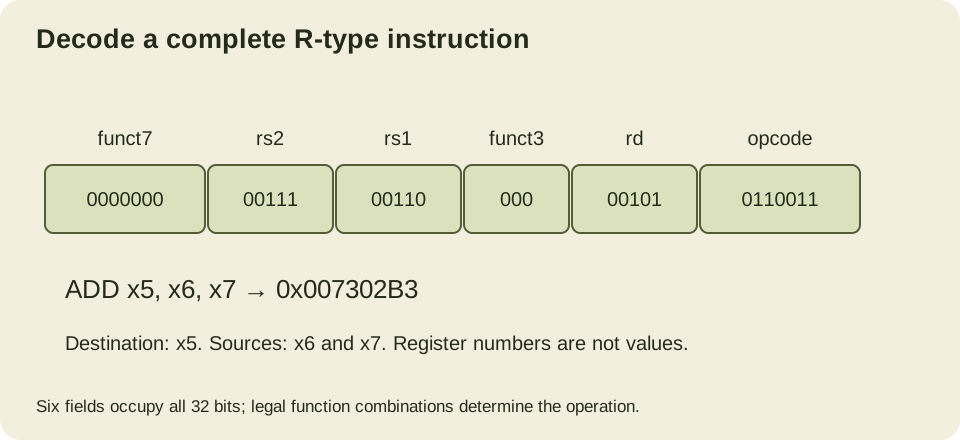
The fixed field locations help a decoder find source and destination register indices while it determines the operation. Other base formats reuse several of these positions even when their remaining bits represent an immediate value.
Extract and reconstruct the word
A field can be extracted by shifting its lowest bit to position zero and applying a mask of the appropriate width. Reconstructing the original word supplies a second check: shift each decoded field back to its location and combine them with OR.
word = 0x007302b3
fields = {
    "opcode": word & 0x7f,
    "rd": (word >> 7) & 0x1f,
    "funct3": (word >> 12) & 0x7,
    "rs1": (word >> 15) & 0x1f,
    "rs2": (word >> 20) & 0x1f,
    "funct7": (word >> 25) & 0x7f,
}
assert fields == {
    "opcode": 0x33, "rd": 5, "funct3": 0,
    "rs1": 6, "rs2": 7, "funct7": 0,
}
rebuilt = (fields["funct7"] << 25) | (fields["rs2"] << 20)
rebuilt |= (fields["rs1"] << 15) | (fields["funct3"] << 12)
rebuilt |= (fields["rd"] << 7) | fields["opcode"]
assert rebuilt == word
print(f"{rebuilt:08x}")
The check covers field arithmetic for this ADD word. Its limitation is that it does not classify or reject other opcodes as a general decoder would. A complete decoder must also check legal function combinations and enabled extensions. Extracting fields from an arbitrary word always produces numbers, even when the word does not encode an instruction supported by the target.
Distinguish ADD from nearby encodings
Changing funct7 from zero to binary 0100000, while preserving this instruction’s other fields, selects SUB in the base integer instruction family. The word becomes 0x407302B3, representing sub x5, x6, x7. The operand indices do not change, but the operation now subtracts x7 from x6.
An immediate addition uses another format and opcode. addi x5, x6, 7 adds the sign-extended constant seven to x6. It does not read x7. This is why a disassembly mnemonic and its operand syntax are useful checks against a raw bit diagram.
The destination also has architectural meaning. Register x0 always reads as zero, and writes to it do not change that value. Encoding rd as zero can discard an arithmetic result, but a general rule that instructions writing x0 have no effects would be wrong. Loads, for example, retain their documented exception behavior even when their result is discarded.
Make the supported subset explicit
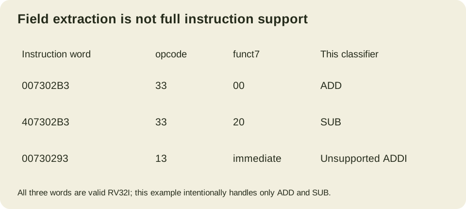
A useful next step is a deliberately narrow classifier that recognizes only ADD and SUB. It must inspect the opcode, funct3 and funct7 together. Matching opcode 0x33 alone is insufficient because several register-register operations share that family. Likewise, a five-bit field at the rs2 position is not always a source register: ADDI assigns those bits to part of an immediate.
The ADDI example above encodes as 0x00730293. Its opcode is 0x13, so the classifier below returns no supported operation for it. That does not make the instruction illegal: ADDI belongs to RV32I, but lies outside this exercise’s two-operation subset. Keep those two decisions separate when writing a debugger, emulator or binary inspection tool. Unknown to one decoder is not the same as prohibited by the target ISA.
def classify_add_sub(word):
    if not 0 <= word < 2**32:
        raise ValueError("one unsigned 32-bit instruction word required")
    if word & 0x7f != 0x33 or (word >> 12) & 7 != 0:
        return None
    return {0: "ADD", 0x20: "SUB"}.get((word >> 25) & 0x7f)

def arithmetic_effect(word, registers):
    operation = classify_add_sub(word)
    if operation is None:
        raise ValueError("outside this ADD/SUB model")
    rd, rs1, rs2 = (word >> 7) & 31, (word >> 15) & 31, (word >> 20) & 31
    left = registers[rs1] if rs1 else 0
    right = registers[rs2] if rs2 else 0
    result = left + right if operation == "ADD" else left - right
    after = list(registers)
    after[0] = 0
    if rd:
        after[rd] = result & 0xffffffff
    return after

assert classify_add_sub(0x007302b3) == "ADD"
assert classify_add_sub(0x407302b3) == "SUB"
assert classify_add_sub(0x00730293) is None  # Valid ADDI, outside this subset.
registers = [0] * 32
registers[6], registers[7] = 0xffffffff, 2
assert arithmetic_effect(0x007302b3, registers)[5] == 1
assert arithmetic_effect(0x407302b3, registers)[5] == 0xfffffffd
rd_zero = 0x007302b3 & ~(31 << 7)
assert arithmetic_effect(rd_zero, registers) == registers
registers[6], registers[7] = 0x7fffffff, 1
assert arithmetic_effect(0x007302b3, registers)[5] == 0x80000000
print("ADD/SUB classification, modular results and x0 discard passed")
The model assumes a list of 32 register bit patterns and evaluates only the arithmetic destination effect. It does not fetch instructions, advance a program counter, handle memory or implement an execution environment. The original register list remains separate from the returned state so the test can compare before and after without confusing a read operand with an already-updated destination.
With x6 equal to 0xffffffff and x7 equal to two, ADD writes one because the carry above bit 31 is discarded. SUB writes 0xfffffffd. With x6 equal to 0x7fffffff and x7 equal to one, ADD writes 0x80000000 even though a signed interpretation crosses from the largest positive value to the most negative. RV32I ADD does not raise an arithmetic overflow exception; software that needs a checked addition must supply the required check.
The destination-zero case verifies that this particular arithmetic instruction discards its result. It cannot justify deleting arbitrary instructions whose rd field is zero. For an exercise, change the source fields so both name x0, then change rd to alias one source register and predict the result using the pre-instruction values. The bit fields determine those dependencies before any pipeline timing enters the discussion.
Keep the instruction word separate from its bytes
In a little-endian byte view, 0x007302B3 appears as bytes B3 02 73 00 at increasing addresses. The opcode still occupies bits six through zero of the instruction word. Reversing displayed byte order without first establishing the memory representation can turn a correct decoder into a confusing exercise.
A binary file also contains data, headers, and possibly instruction encodings of different lengths when extensions are enabled. Starting at an arbitrary byte and treating every four bytes as RV32I instructions is not a reliable disassembly strategy. You need the executable format, entry points, architecture attributes, and instruction alignment rules.
An assembler or disassembler can automate the process, but aliases may hide the underlying instruction. A displayed mv or nop can correspond to a base instruction with particular operands. For this ADD, the example uses explicit x-register names to avoid adding ABI aliases before the encoding is understood.
Use the decode to answer a software question
Suppose a compiler emitted this ADD inside a loop. The encoding tells you which architectural registers it reads and writes. It does not tell you whether the operation will stall, which physical execution unit handles it, or whether another instruction issues in the same cycle. Those are microarchitecture and workload questions.
The instruction contract is still useful evidence. It lets you distinguish a register operand from an immediate, identify a true dependency, and check whether the binary targets the intended ISA. Read those facts from the specification first, then use implementation documentation or measurements for claims about speed. A precise 32-bit decode is a small result, but it is one you can independently reconstruct.